We recently walked you through static axial seals. Now that we’ve taken a look at several different seal types, we’re going to cover gland design and selecting the optimum O-Ring size.
Our table lists SAE recommended dimensions for static axial seal glands by ascending AS568 Oring numbers. A key advantage in accommodating an O-Ring size from this chart is the availability from stock. We stock AS568 O-Ring sizes in several materials and durometers. For more information, refer to our Static Axial Seal Gland Dimensions:
Gland Depth of Static Axial Seals
Take special note on dimension H, gland depth. This represents the distance from the bottom of the gland (green plate) to the surface of the cover (blue plate). H is commonly mistaken for the depth of the groove on the green plate. H will be affected if the plates are neither flat nor parallel. A gap will be present which will act as an extrusion path for the O-Ring. O-Ring extrusion is a common failure mode in high pressure applications.
If none of the listed sizes fit in the application, the next option is to consider the non-standard O-Ring sizes. “Non-standard” does not necessarily mean custom parts, it just means that they fall in between the AS568 sizes. Apple Rubber also keeps these non standard sizes in stock. You can also visit our O-Ring Search for available O-Ring sizes.
Consider an external pressure situation with an inner groove wall of Ø.389in. Due to material constraints, the max gland depth is .029in. The plates are flat and parallel, therefore H = .029in. The AS568 sizes will not work. Consider a non-standard oring.
Calculate the percent compression on the O-Ring cross section. The recommended compression on a static axial O-Ring seal is 25 percent. Fitting a Ø.039W oring cross section diameter in a .029in(H) gland height will yield a 25 percent compression.
Have questions on percent compression? We provide a guideline for recommended percent compression for varying O-Ring cross sections.
So, how much force is required to compress an Ø.039W O-Ring 25 percent? This force can be used to determine how many bolts are required for the cover. Another use can be to determine if the hardware material has sufficient compressive stress to counteract the O-Ring force. The force required for a different percent squeeze, non-standard cross section, and/or durometer can be inferred from the generally linear relationship between the three factors and force required.
Calculating Groove Width
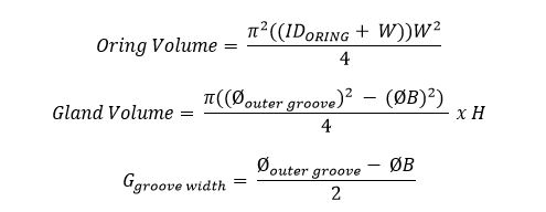
The groove width is a major factor of gland fill. Gland fill is the percentage of gland volume that an O-Ring cross section displaces in its confining gland. Gland fill is recommended between 60 and 85 percent. The groove width can be adjusted to meet this condition. Minimum gland volume should be 10 percent larger than maximum O-Ring volume.
G = .054in results in a 74 percent gland fill satisfying the gland fill recommendations.
A quicker but less precise method is using cross sectional area to calculate gland fill. The same gland fill percentages apply: 60 – 85 percent.
Recapping the Design: We have an external pressure situation with an inner groove wall of Ø.389in. This puts the optimum oring ID = Ø.394in. Due to hardware material constraints, the max gland depth is .029in. The plates are flat and parallel. In this case, H = .029in. Using the percent compression equation, Ø.039in cross section diameter oring results in a 25 percent compression. Using the volume equations, a .054in groove width = G results in a 74 percent gland fill.
The details of the groove design are completed by specifying the proper radii and finish as indicated in the Static Axial Seal Gland Dimensions Table. Whether it is an AS568 size or a non standard size, the radii and surface finish call-outs from this chart apply.
The target O-Ring here is: .394ID x .039W.
Have questions on O-Rings? Need help searching for available O-Ring sizes? We’d love to help.


